Frozen
Here is an active version
3.3V 5V
There is such a chip Max 7219, which is a seven-segment indicator controller. It not only allows to control eight such indicators, but also allows cascading connection with the same controllers, which allows to arbitrarily increase the bit capacity.
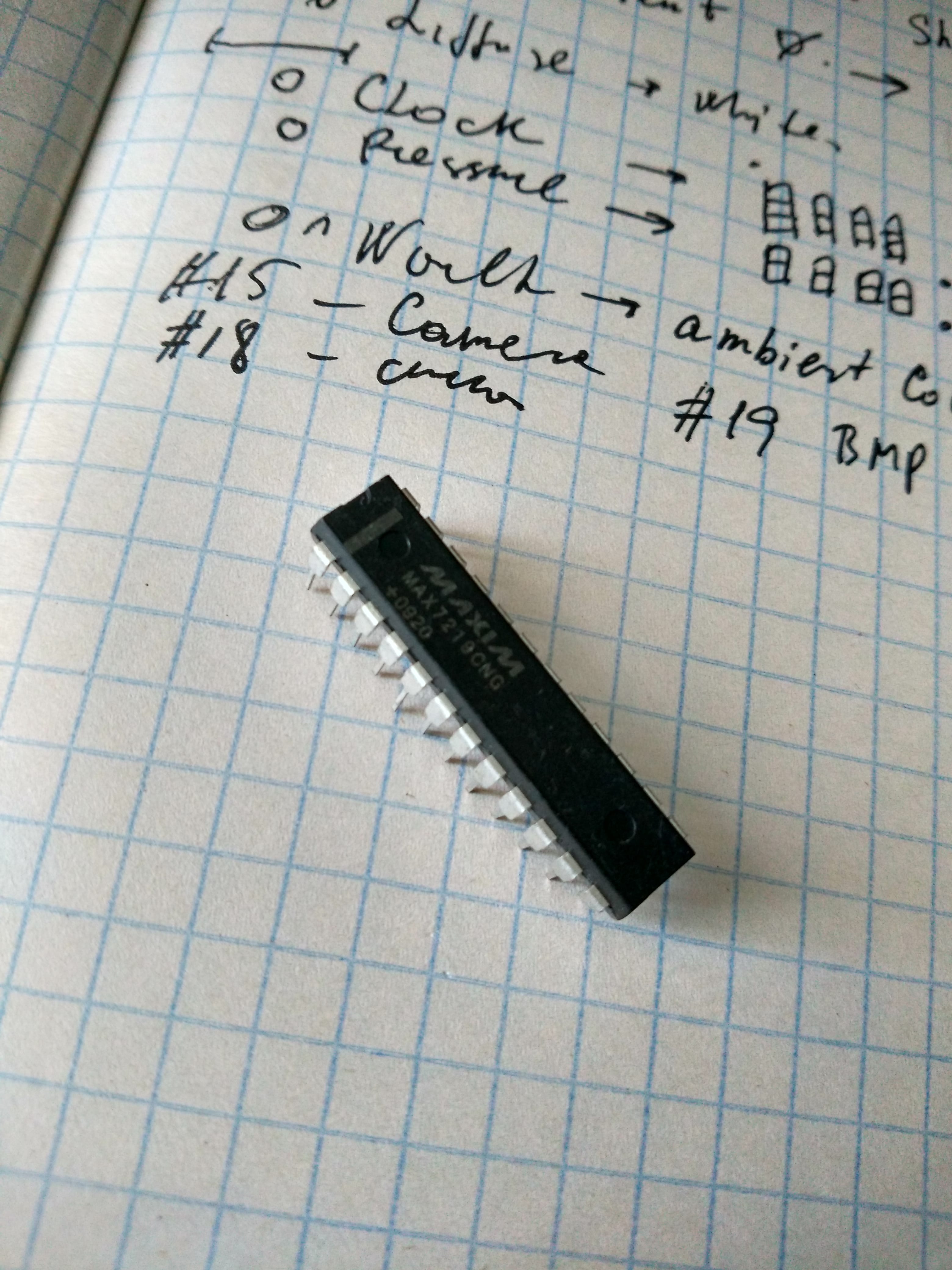 This chip seemed to be a suitable candidate for my project ``Gorilla ‘’, but it has some features, in particular it has a supply voltage of 5V and, respectively, TTL logic levels.
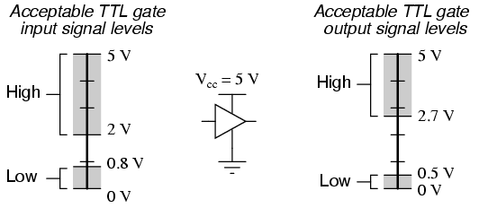
The outputs are connected to the LED and the next same chip, so they do not interest us. There remain three inputs: CLK, LOAD and DIN. Since the GPIO Raspberry Pi outputs are CMOS, then the voltage is used to represent the logical zero, and for the logical 1 representation a voltage is used.
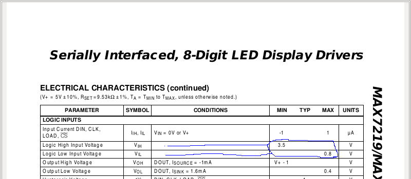
It would seem all right and we fall into the right range of TTL logic, but the documentation for the chip indicates that the minimum allowable voltage for a logical 1 is 3.5V, which completely eliminates the possibility of control from Raspberry Pi 1.
So we need a logical level converter.
MOSFET as a converter
Consider the following simple scheme:
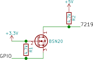
Two pull-up resistors provide a logical 1 on both sides of the converter. So, if the logic output is set at the GPIO output, then the voltage drop across the resistor , the transistor is closed and input 7219 is set high due to the pull-up resistor .
If the GPIO output is set to logic zero, voltage on drops 3.3V, the transistor opens and at the input 7219 gets a zero potential.
Our converter is working.
But the most remarkable thing is that thanks to the built-in diode this converter works in the opposite direction!![]()
With logical 1, everything is clear and uninteresting, let’s see what happens if 7219 is an output on which a logical zero is set. Then the current starts flowing through the built-in diode, something about falls on it, therefore a voltage drop is formed on the resistor , the transistor is opening, and voltage drop on became all 3.3V effectively forming a logic zero at the input GPIO.
Implementation
The BSN20 transistors turned out to be very small:
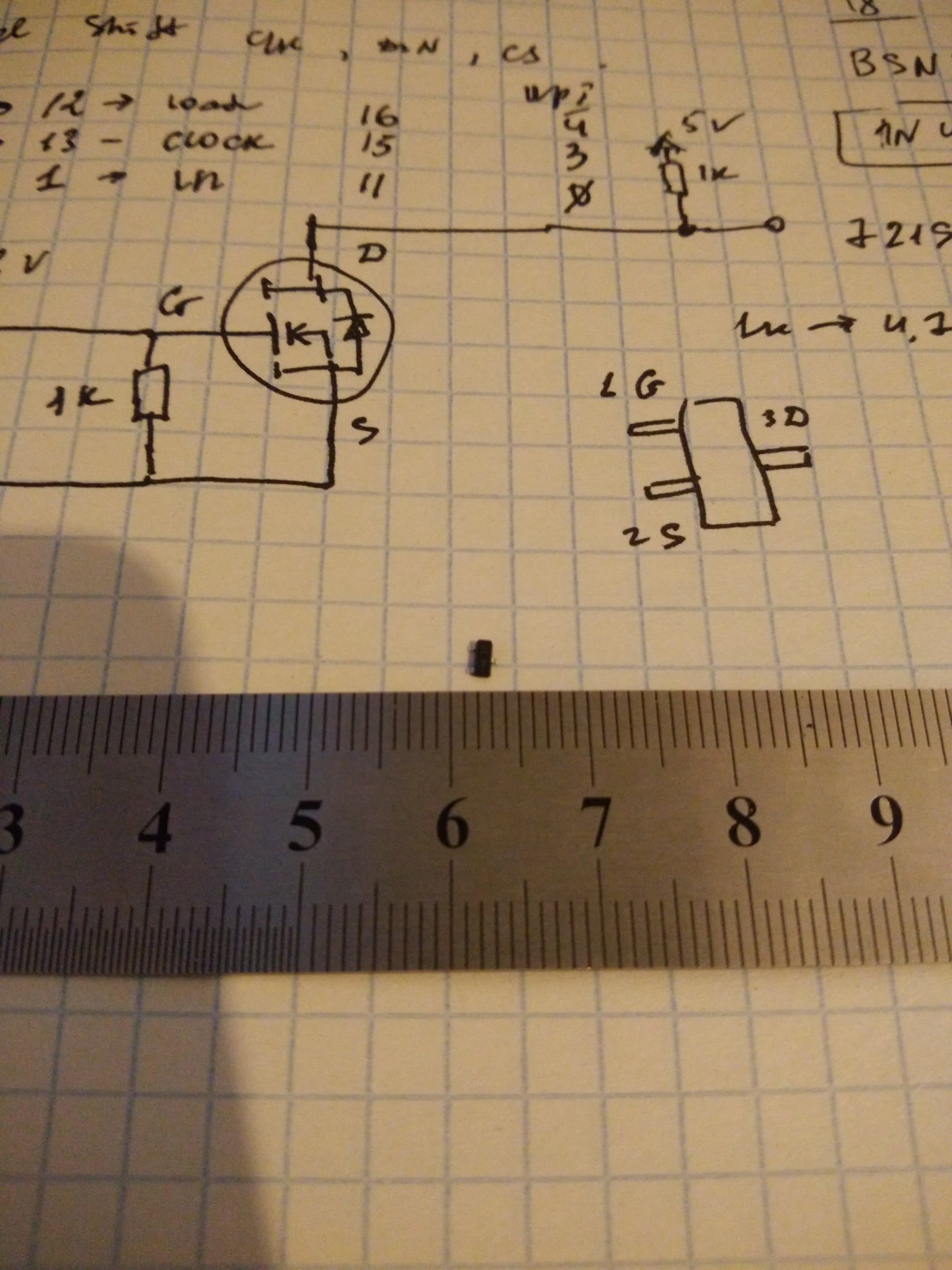
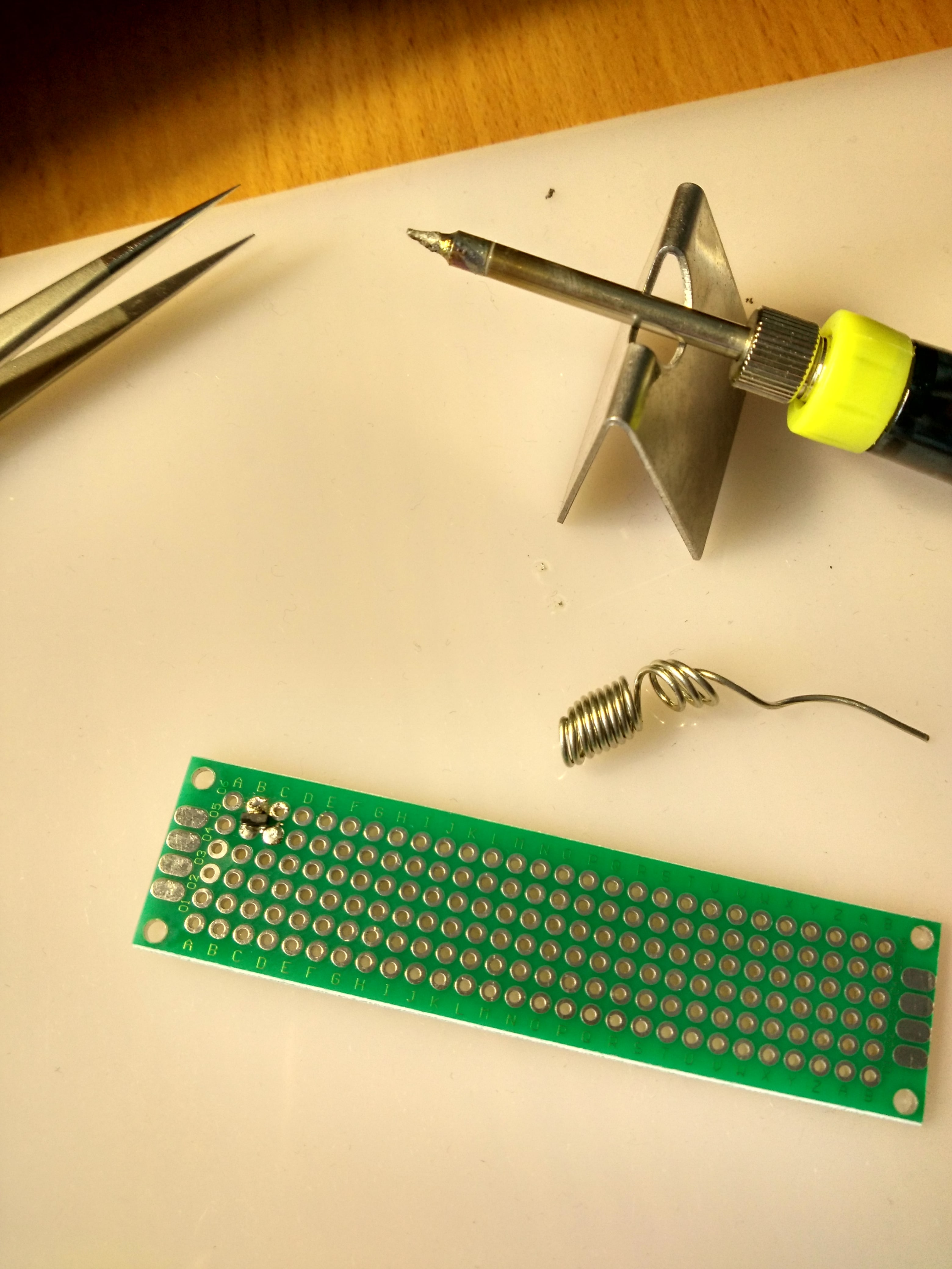
Let’s try soldering on the prototyping board one transistor:
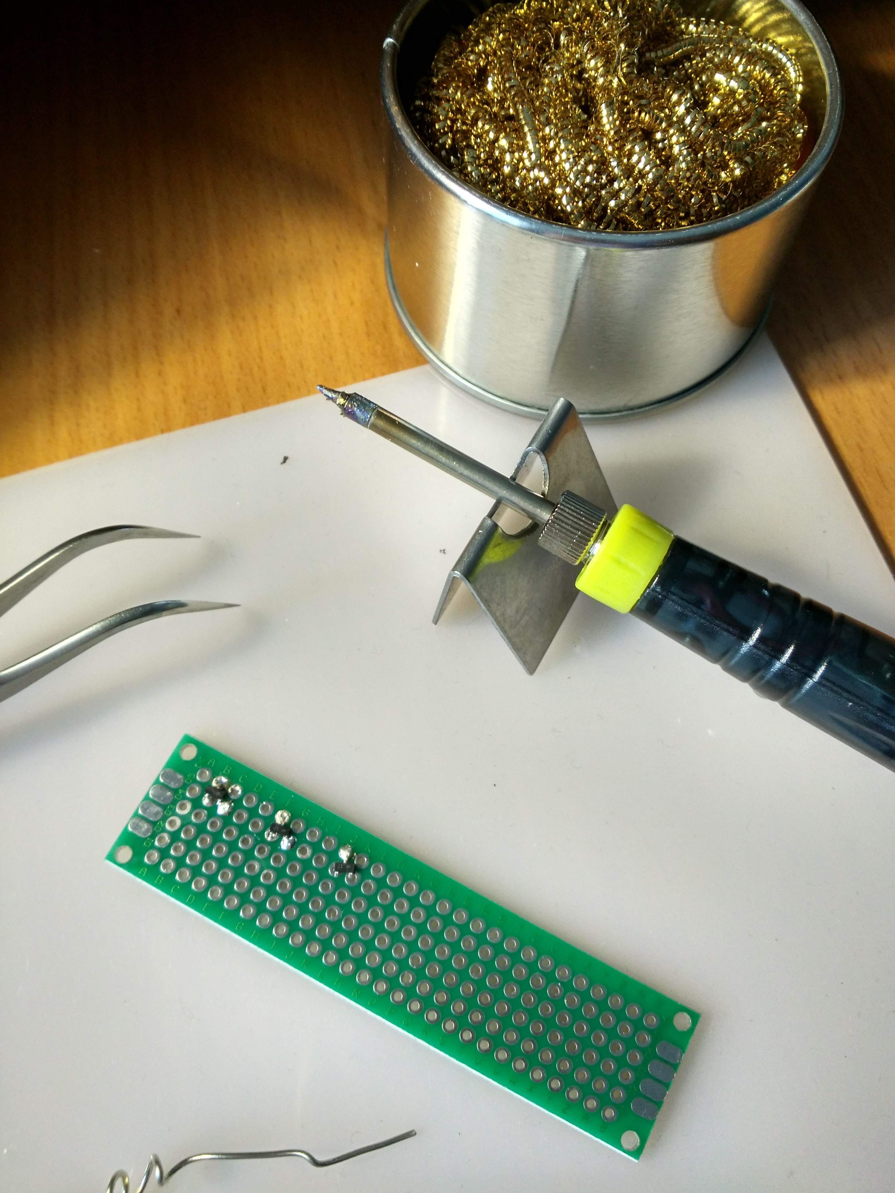
And two more for the remaining lines:
Adding resistors:
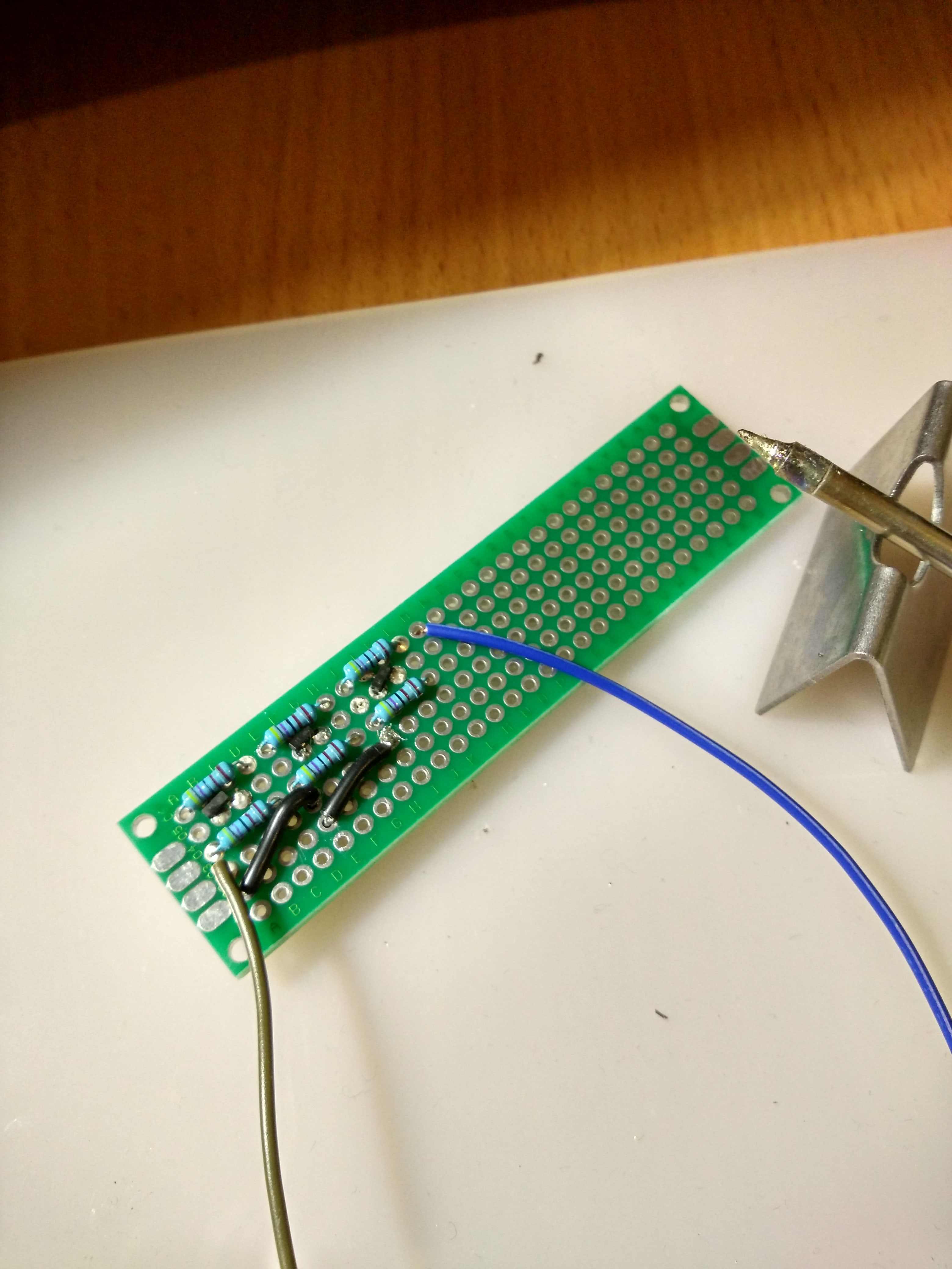
Everything is here:
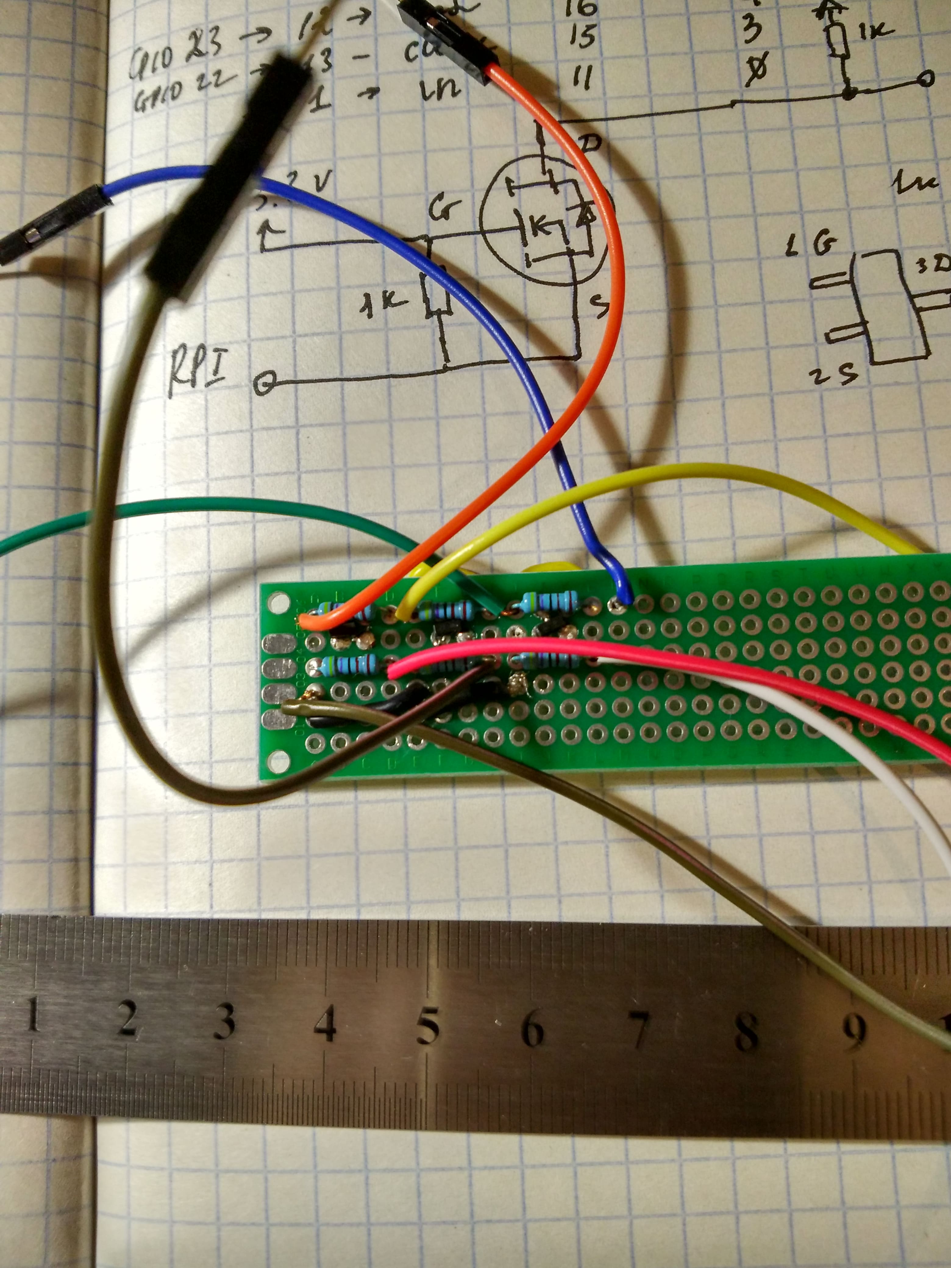
Check the converter
Well, at the same time and 7219
The converter works just fine, but 7219 is dead. ![]()
-
It should be noted that the network is full of descriptions of the successful connection of this chip to Raspberry Pi. I do not know how it goes, it is possible that the scatter of parameters in individual chips allows them to work at a lower logical 1 level. ↩

