Frozen
Here is an active version
Sensors with one-wire connection
1-wire - is a system of communication between devices, developed by Dallas Semiconductor Corp, which provides low-speed data exchange and power by a single wire.
A distinctive feature of this bus is the ability to use only two wires: data and ground. To achieve this, the device includes a 800pF capacitor for storing power and powering the device when using the data line.
Let’s look at one of these things that I found at hand: DS18B20.
Datasheet
First of all we read the documentation to understand whether this device is suitable and what its capabilities are. So:
- Can be powered from a data line from 3.0V to 5.0V. It’s good.
- The accuracy of in the range from to .
- Current consumption in the measurement mode: from to .
Further in the documentation there is a circuit:
 which I do not like. GPIO output as we saw earlier consists of two transistors. If we set the output low (actually connect to the ground) and at the same time open the pull-up transistor in the proposed scheme, we get fried Raspberry Pi
![]() I do not want to take that risk.
I do not want to take that risk.
The simpler circuit
So, we put a resistor, which gives , if the current is too small to measure the temperature, then we reduce the resistance.

Software
Why GPIO4? Let’s read /boot/overlays/README:
Name:   w1-gpio
Info:   Configures the w1-gpio Onewire interface module.
        Use this overlay if you *don't* need a GPIO to drive an external pullup.
Load:   dtoverlay=w1-gpio,<param>=<val>
Params: gpiopin                 GPIO for I/O (default "4")

        pullup                  Non-zero, "on", or "y" to enable the parasitic
                                power (2-wire, power-on-data) feature


Name:   w1-gpio-pullup
Info:   Configures the w1-gpio Onewire interface module.
        Use this overlay if you *do* need a GPIO to drive an external pullup.
Load:   dtoverlay=w1-gpio-pullup,<param>=<val>
Params: gpiopin                 GPIO for I/O (default "4")

        pullup                  Non-zero, "on", or "y" to enable the parasitic
                                power (2-wire, power-on-data) feature

        extpullup               GPIO for external pullup (default "5")
The overlay w1-gpio-pullup is not our option1, but w1-gpio looks attractive. So we will add next line into the file /boot/config.txt:
dtoverlay=w1-gpio,gpiopin=4
Attention
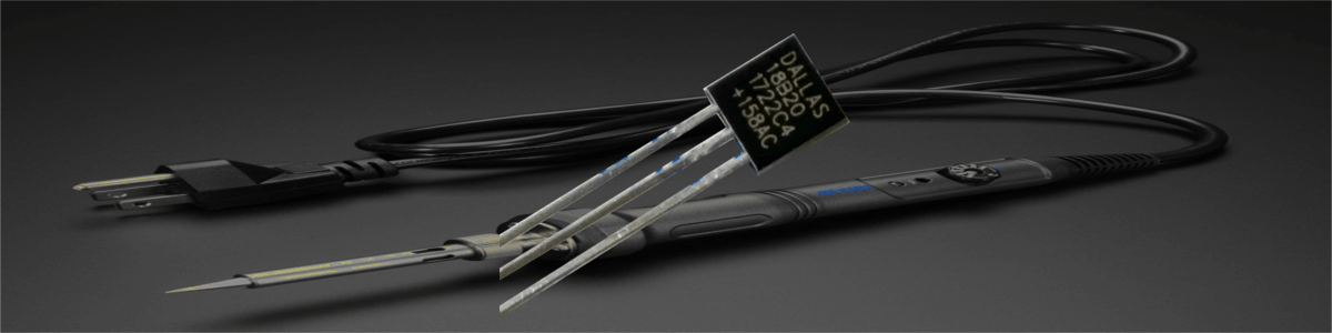
As it turned out, not all yogurts are equally useful (btw, yoghurts are not useful at all, in any way). Some of the DS18B20 are not very successful fakes. In particular, I got both +158ac2 chips that do not work in parasitic mode, that is, I will have to apply voltage to the chips separately:

Breadboard


Check the detection of the thermometer and the correctness of the readings:

looks quite plausible![]()
Multiple sensors
This is the last thing I would like to try today, after all it’s still a tire. To begin with, we will make changes to the breadboard:


Let’s look:

The error fits into the declared accuracy .![]()