Frozen
Here is an active version
The Light is so Simple
As a person who does not know which end to hold the soldering iron, I’m very afraid of damaging Raspberry Pi. Therefore I want to get a clear idea of how these GPIOs are designed not to fry them.
Simply put, each GPIO can be represented as a pair of MOSFETs:

Do not pay attention to the diodes, in theory they are designed to provide protection from the static of the wrong polarity, In practice, you can still kill the IC by a static charge.
So, we have two transistors, one of which is open. Which one? Depends on the level on the Input: if there is
0, then open U2 (it has a channel type P and it narrows with a positive charge on the gate 1), if the same
there is a 1, then U1 is opened (it has a channel of the type N and it expands with a positive charge on the gate 1).
But the funny thing is that the current through transistors is not limited in any way.
Valid and initial values
Voltage. It’s all just — 3.3V.
Current. Can be programmed as 2, 4, 6, 8, 10, 12, 14 or 16 mA. However, there is a catch: all GPIO should consume no more than 50 mA together. The initial value is not documented anywhere, it is assumed that all outputs operate at 8 mA. In addition, the programming of a certain current means only that at this current discrimination of the levels of the logic voltage is guaranteed.
That is, the current will be consumed by the one that is required for loading, regardless of the programmed one, but it should not be consumed more than 16 mA.
Circuit calculation
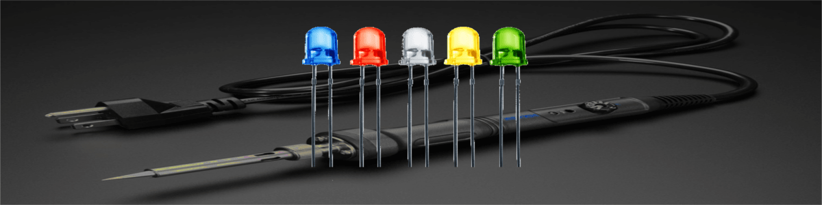
So we have the LED:

From wikipedia we look through the table of voltage drops on 20 mA 5mm LEDs of different colors:
| Color | Voltage drop |
|---|---|
| red | |
| yellow | |
| green | |
| blue |
Let the current through the diode be 8 mA, we’ll notice the glow. Let the voltage drop on the diode is the worstest — 2.48 V. The remaining voltage should fall on the resistor R1.
 Voltage drop at the resistor is . At a current of 8mA, the resistance of the resistor
 R1
is equal to . I have and resistors:

Let’s see how much more current I will get at : A. This can o neglected. However, in other similar cases it is better to increase the resistance, since the current decreases at the same time, and, as a rule, a smaller current is good.
Check on the breadboard
I have a small power supply that I can use to test the circuit before connecting to Raspberry Pi:
 Regulators AMS1117, on which this unit is built, are described as protected from short circuit and temperature
overload, so that nothing terrible will happen if there are errors in the circuit or calculations.
Regulators AMS1117, on which this unit is built, are described as protected from short circuit and temperature
overload, so that nothing terrible will happen if there are errors in the circuit or calculations.
You just need to remember that the maximum input voltage is 15V.
Let’s make the circuit on a breadboard:

And check the voltage on the resistor:

0.1V, then a voltage drop on my LED is more than calculated![]() .
Calculate the current:
.
Calculate the current:
A
Not bad. The LED lights up, the current is completely safe, I can go directly to Raspberry Pi. But about that next time: smiley: